Every forging and every casting contains discontinuities. The question is never whether they are there, but whether any of them sits where the stress is, is large enough to matter, and will be found before the part is installed. A lap on a shaft shoulder and the same lap on an unloaded face are not the same problem, and treating them as one is how inspection budgets get spent in the wrong places.
Below: the defects we actually see on forged and cast parts, what causes each one, which method finds it, and at what point in the route it is cheapest to look.
What undetected defects really cost
A defect caught in manufacturing costs very little. The same defect after installation costs many times more.
Cost escalation through the supply chain
| When detected | Typical cost to resolve | Impact |
|---|---|---|
| During manufacturing | €50–200 | Scrap material, remake the part |
| Incoming inspection | €500–2,000 | Return shipping, replacement lead time, inspection cost |
| During assembly | €2,000–10,000 | Production delay, expedited replacement, wasted labour |
| After installation | €10,000–50,000 | Field service, equipment downtime, emergency shipping |
| Catastrophic failure | €50,000–1,000,000+ | Liability, safety incidents, reputation damage, recalls |
Why the cost curve is so steep
Consider a forged pump shaft with incomplete closure at the centre — a defect that visual inspection cannot see and a scan to EN 10228-3 finds in minutes. Caught at the forge, it costs a re-forge. Caught after the part is turning in a chemical plant, the shaft itself is the cheapest item on the invoice: the plant stoppage, the field service call, and the inspection of every sister part already in stock all arrive first.
This is the whole argument for volumetric testing on rotating and pressure-retaining parts. It is not that UT catches everything. It is that the things it catches are precisely the ones you cannot see and cannot afford to find later.
Where zero defects is the requirement
In some industries defects are not merely expensive, they are unacceptable:
- Nuclear: Regulatory requirements for complete traceability and defect-free material
- Aerospace: Safety-critical components with rigorous inspection protocols
- Oil and gas: High-pressure applications where failure endangers people
- Automotive safety: Components acting on vehicle safety systems
- Medical devices: Patient safety and regulatory compliance
Common defects in forged components
1. Surface defects
Laps and folds
What it is: Surface material that folds over itself during forging, creating a discontinuity or seam on the surface.
Causes: Improper die design, insufficient material, incorrect forging temperature or inadequate reduction ratios.
Why it matters: Creates stress concentrations and crack initiation sites. Can trap scale or oxides. Propagates under cyclic loading.
Detection: Visual inspection, magnetic particle testing (MT), dye penetrant testing (PT)
Prevention: Proper die design, correct stock sizing, optimal forging temperature, adequate reduction between passes
Surface cracks
What it is: Visible cracks on the forged surface, typically oriented perpendicular to the forging direction.
Causes: Excessive forging temperature (hot shortness), improper cooling rates, contaminated material or excessive deformation.
Why it matters: Even small surface cracks propagate under stress and lead to failure. Especially dangerous in fatigue applications.
Detection: Visual inspection (large cracks), MT or PT (fine cracks), sometimes visible after acid etching
Prevention: Control forging temperature carefully, avoid overheating, controlled cooling, material quality control
Scale and decarburisation
What it is: Oxide formation on the surface and carbon loss in the surface layer during hot forging.
Causes: Exposure to oxygen at high temperature during heating and forging.
Why it matters: The decarburised layer is softer and weaker. Affects fatigue life and wear resistance. Scale must be removed before heat treatment or coating.
Detection: Visual inspection (scale), hardness testing (decarburisation), metallographic examination
Prevention: Controlled atmosphere heating, minimise time at temperature, shot blasting or pickling, adequate machining allowance
2. Internal defects
Internal cracks and bursts
What it is: Fractures inside the forging, not visible on the surface. Centreline cracks, chevron cracks or random internal fissures.
Causes: Excessive reduction without adequate heating, internal stress from improper cooling, contaminated material or hydrogen embrittlement.
Why it matters: Invisible to visual inspection but catastrophic in service. Can cause sudden failure under load.
Detection: Ultrasonic testing (UT) is the primary method. Radiography detects large cracks but is less effective than UT on forgings.
Prevention: Sound forging practice, adequate heating, controlled cooling, quality raw material, stress relief where required
Incomplete die filling and cold shuts
What it is: Areas where metal did not flow completely into the die cavity, leaving voids or weak bonds between flow fronts.
Causes: Insufficient material, forging temperature too low, inadequate press capacity or complex die geometry.
Why it matters: Creates weak areas with significantly reduced strength. May look sound from outside.
Detection: Visual inspection (edge underfill), UT (internal voids), dimensional and weight checks
Prevention: Proper stock design, adequate forging temperature, sufficient press capacity, optimised die design
Poor grain flow
What it is: Grain flow not aligned with the part geometry, or fibre cut through by excessive machining.
Causes: Improper forging design, excessive material removal, or forging in the wrong orientation.
Why it matters: Negates the primary advantage of forging — directional strength. Reduces fatigue life and toughness.
Detection: Macro-etching to reveal the grain flow pattern, mechanical testing in different orientations
Prevention: Design parts for forging, minimise machining depth, orient the forging to match the load path
Inclusions and segregation
What it is: Non-metallic particles in the steel matrix, or local concentration of alloying elements.
Causes: Poor steelmaking practice, contaminated scrap, inadequate refining. Present in the raw material, not created by forging.
Why it matters: Create stress concentrations, reduce ductility and act as crack initiation sites.
Detection: UT (large inclusions), metallographic examination, chemical analysis of suspect areas
Prevention: Quality raw material from reputable suppliers, verified mill certificates, UT of raw stock for critical applications
Common defects in cast components
1. Porosity and shrinkage
Gas porosity
What it is: Small, rounded voids from gas bubbles trapped during solidification. Dispersed or locally concentrated.
Causes: Dissolved gases (hydrogen, nitrogen, oxygen) in the melt, moisture in the mould, inadequate venting or turbulent pouring.
Why it matters: Reduces mechanical properties, especially fatigue strength, creates leak paths in pressure-containing parts and impairs machinability.
Detection: Radiographic testing (RT), pressure testing for through-porosity, visual inspection of machined surfaces
Prevention: Degas the melt, dry moulds, proper gating and venting, controlled pouring, vacuum casting for critical parts
Shrinkage cavities
What it is: Voids created when the metal contracts during solidification without adequate feeding from risers. Typically irregular in shape.
Causes: Insufficient riser size, poor riser placement, isolated hot spots or an interrupted feeding path.
Why it matters: Severe reduction in mechanical properties. Large and critical in heavy sections. Creates unpredictable failure points.
Detection: RT, UT, visual inspection if near the surface or exposed by machining
Prevention: Proper riser design, directional solidification, adequate feeding, solidification simulation
Microporosity
What it is: Fine, distributed porosity throughout the casting, usually in the last regions to solidify.
Causes: A combination of gas evolution and shrinkage, particularly in alloys with a wide solidification range.
Why it matters: Reduces properties subtly, is often missed by standard inspection, and accumulates over the volume.
Detection: Difficult to detect; density measurement, destructive testing, detailed radiography
Prevention: Control the solidification rate, grain refiners, suitable alloy selection, hot isostatic pressing (HIP) for critical parts
2. Mould-related defects
Sand inclusions
What it is: Sand particles embedded in the casting surface or through the volume (a sand casting defect).
Causes: Mould erosion during pouring, loose sand from the mould surface, inadequate mould strength or excessive turbulence.
Why it matters: Rough surface finish, potential stress concentrators, machining difficulties, reduced fatigue life.
Detection: Visual inspection, RT (large inclusions), grinding to establish depth
Prevention: Proper mould compaction, adequate binder systems, smooth mould surfaces, controlled pouring, filters in the gating system
Cold shuts and misruns
What it is: Areas where two metal streams meet without fusing (cold shut), or incomplete filling of the mould cavity (misrun).
Causes: Low pouring temperature, insufficient fluidity, slow pouring or complex geometry with thin sections.
Why it matters: Creates planes that look fused but have no metallurgical bond. High risk of failure under stress.
Detection: Visual inspection (often visible), PT, sometimes RT, pressure testing
Prevention: Adequate pouring temperature, proper gating design, sufficient fluidity, rapid pouring
Surface roughness
What it is: Rough or irregular casting surface, outside the specified finish requirement.
Causes: Coarse sand, mould moisture, metal–mould reaction or inadequate mould coating.
Why it matters: More machining required, can conceal other defects, cosmetic issues.
Detection: Visual inspection, surface roughness measurement
Prevention: Fine moulding sand, proper mould coatings, investment casting for a superior finish, good pattern quality
3. Metallurgical defects
Hot tears
What it is: Cracks forming during or immediately after solidification, while the metal is still hot and contracting.
Causes: Restrained contraction, rapid cooling, design with stress concentrators, or alloys susceptible to hot cracking.
Why it matters: Can propagate in service, create leak paths and reduce structural integrity.
Detection: Visual inspection (if at the surface), PT (fine cracks), RT
Prevention: Design for uniform cooling, avoid restraining features, suitable alloy selection, controlled cooling rates
Slag, dross and oxide inclusions
What it is: Non-metallic particles trapped in the casting: slag from melting, dross from the surface, or oxide films.
Causes: Inadequate melt cleaning, turbulent pouring entraining slag, oxide formation during pouring.
Why it matters: Stress concentrations, reduced ductility, crack initiation sites, reduced corrosion resistance.
Detection: RT, UT (large inclusions), metallographic examination, fracture surface analysis
Prevention: Proper melt treatment, skimming, filters in the gating system, controlled pouring, bottom-pour ladles
Segregation and microstructural issues
What it is: Non-uniform distribution of alloying elements or undesirable microstructural features.
Causes: Slow cooling rates, large section sizes, alloy compositions prone to segregation.
Why it matters: Non-uniform mechanical properties, unpredictable performance, localised weakness.
Detection: Metallographic examination, hardness surveys across the casting, chemical analysis at several locations
Prevention: Controlled cooling, suitable alloy selection, solution heat treatment where applicable, inoculants and grain refiners
Non-destructive testing: finding defects before they cause failures
No single method finds everything. The skill is matching the method to the expected defect — and knowing what it cannot do.
The principal methods at a glance
| Method | Best at finding | Forging | Casting | Limitations |
|---|---|---|---|---|
| Visual inspection (VT) | Surface defects, dimensional issues | ✓ Basic check | ✓ Basic check | Surface only, subjective |
| Ultrasonic testing (UT) | Internal cracks, inclusions, voids | ✓✓ Excellent | ✓ Good | Requires skill, geometry dependent |
| Radiographic testing (RT) | Porosity, shrinkage, inclusions | ✓ Less common | ✓✓ Excellent | Radiation safety, 2D image of a 3D structure |
| Magnetic particle (MT) | Surface and near-surface cracks | ✓✓ Excellent | ✓ Limited (ferrous only) | Ferromagnetic materials only, surface prep needed |
| Dye penetrant (PT) | Surface-breaking defects | ✓✓ Excellent | ✓✓ Excellent | Surface only, clean surface required |
| Eddy current (ET) | Surface cracks, conductivity variation | ✓ Specialised | ✓ Specialised | Conductive materials, shallow depth |
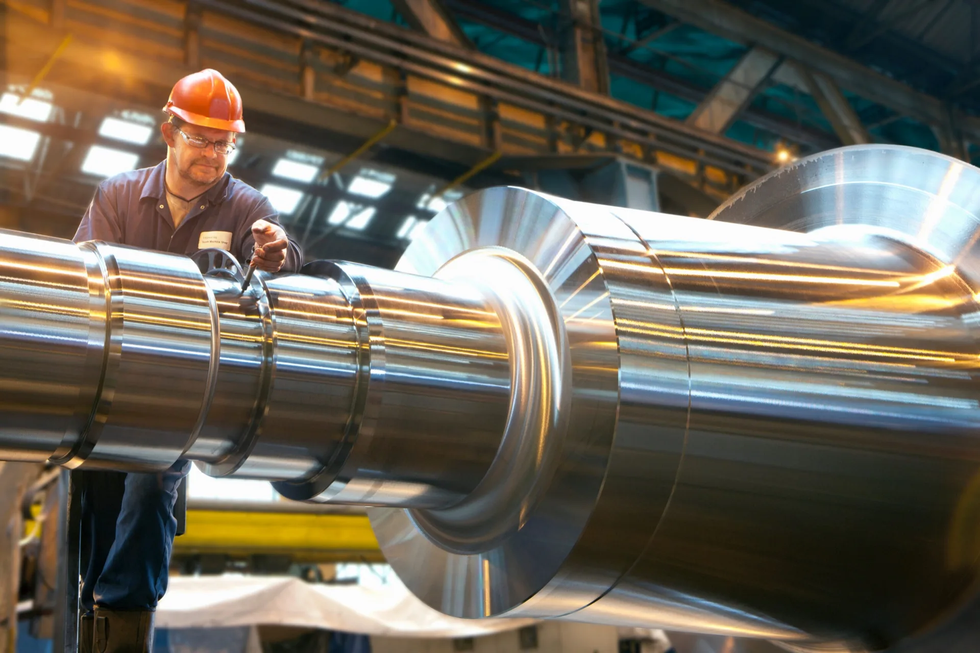
Ultrasonic testing on a forged component — the workhorse for internal defects.
1. Visual inspection (VT)
When to use
On every component, as the first and cheapest stage of any inspection sequence.
What it catches
Coarse surface cracks, laps, misruns, scale, form defects, obvious dimensional deviations.
Limitations
Surface only, heavily dependent on the inspector, finds nothing below the skin.
Good practice
Defined lighting, trained personnel, reference samples for the acceptance limit, photographic records.
2. Ultrasonic testing (UT)
The workhorse for forgings
For internal defects in forgings, UT is the primary method. The dense, worked structure transmits ultrasound well, which allows high-sensitivity examination through the full section.
Advantages on forgings
Covers the whole volume, high sensitivity to planar defects, immediate result, no radiation safety requirements.
What it detects
Internal cracks, laminations, large inclusions, shrinkage, incomplete closure at the centre.
Requirements
Suitable surface, accessible geometry, qualified operator, quality class to EN 10228-3 or customer specification.
Limitations
Complex geometry complicates interpretation, coarse cast structure scatters the beam, the result depends on operator skill.
3. Radiographic testing (RT)
The benchmark for castings
On castings, radiography is the reference method. Porosity and shrinkage are volumetric defects that image well on film — unlike the planar defects ultrasound is strong on.
Advantages on castings
Images porosity and shrinkage clearly, produces a permanent record, can be graded against reference radiographs.
What it detects
Gas porosity, shrinkage cavities, slag and sand inclusions, cold shuts, larger cracks.
Requirements
Controlled radiation area, access from both sides, limited wall thickness, evaluation to ASTM E446 or equivalent.
Limitations
A two-dimensional image of a three-dimensional structure; planar defects perpendicular to the beam are hard to see; slow and costly.
4. Magnetic particle testing (MT)
How it works
The part is magnetised; particles applied to the surface gather at disturbances in the field and outline the defect.
Best applications
Ferromagnetic forgings, machined surfaces, welds — anywhere surface cracking is the main risk.
What it finds
Surface and near-surface defects to a few millimetres deep, laps, quench cracks.
Limitations
Ferromagnetic materials only — not applicable to austenitic stainless. Needs surface preparation and demagnetisation afterwards.
5. Dye penetrant testing (PT)
How it works
A penetrant is applied, the excess removed, and a developer draws it back out of the defect where it becomes visible.
Best applications
Austenitic stainless and other non-magnetic materials, castings, anywhere MT cannot be used.
What it finds
Surface-breaking defects only: cracks, pores, cold shuts, hot tears.
Limitations
Open defects only — a crack below the surface stays invisible. Requires a clean, unsmeared surface.
Inspection strategy: what to test, and when
Not every component needs every test. A sensible strategy matches the methods to the criticality of the application and the likely defect modes.
Risk-based inspection
| Criticality | Forging inspection | Casting inspection |
|---|---|---|
| Safety-critical (nuclear, aerospace, pressure vessels) | 100% UT · 100% MT or PT · dimensional inspection · mechanical testing per lot · certificate verification | 100% RT · 100% PT · pressure testing · mechanical testing per lot · metallographic examination |
| High-value / high-stress (gearbox shafts, pump components) | 100% UT · sample MT/PT (10–20%) · dimensional inspection · certificate review | 100% RT or UT · sample PT · pressure test if applicable · dimensional inspection |
| Standard industrial (general machinery) | Sample UT (first article + 10%) · 100% visual · dimensional inspection · certificate review | Sample RT (first article + random) · 100% visual · dimensional inspection · certificate review |
| Low-stress (covers, brackets, bases) | 100% visual · dimensional inspection · certificate on file | 100% visual · dimensional inspection · pressure test if applicable |
Our approach: first article plus production monitoring
First article inspection
- Comprehensive inspection of the initial pieces
- 100% of the applicable NDT methods
- Complete dimensional verification
- Mechanical property testing
- Metallographic examination for critical applications
- Establishes the baseline for production acceptance
Production monitoring
- Risk-based sampling frequency
- 100% visual and dimensional on all parts
- NDT sampling based on criticality (10–100%)
- Increased frequency if issues are detected
- Continuous supplier performance tracking
Stage gates: catching defects early
The most effective quality strategy catches defects at the earliest possible stage:
Raw material verification
- Review mill certificates (EN 10204 3.1 minimum)
- Verify heat numbers and traceability
- Chemical analysis where required
- UT of raw stock for critical applications
Catches: Wrong material, defects already present in the raw stock
In-process inspection
- Check after forging or casting, before machining
- Visual inspection for surface defects
- Dimensional verification of critical features
- NDT where defects are suspected
Catches: Manufacturing defects before expensive machining
Final inspection after machining
- Complete dimensional inspection
- Surface finish verification
- Full NDT per specification
- Functional testing if applicable
- Cleaning and packaging inspection
Catches: Any remaining defects before shipment
Receiving inspection
- Visual inspection for shipping damage
- Review of the documentation package
- Sample dimensional verification
- Risk-based NDT sampling for critical components
Catches: Final verification before acceptance into inventory
Prevention beats detection
Thorough inspection catches defects — preventing them is more effective and cheaper. The best quality programmes stop defects arising in the first place.
Supplier selection and qualification
Process capability
Suppliers with the right equipment, technical expertise and a proven record for your specific components.
Quality systems
ISO 9001 as a minimum. Industry-specific certification (AS9100, API, nuclear QA) where applicable. Demonstrated statistical process control.
Material sources
Reputable material suppliers, verified certificates, traceability systems, in-house testing capability.
Inspection equipment
Appropriate NDT equipment and certified operators, calibrated measuring equipment, in-process monitoring.
Design for manufacture
Preventing defects through good design
- Forgings: Avoid sharp corners and stress concentrators. Design for a load-carrying grain flow. Provide adequate machining allowance. Consider die filling in closed-die designs.
- Castings: Uniform wall thickness where possible. Generous fillet radii. Design for directional solidification. Include feeding paths to risers. Avoid isolated hot spots.
- Both: Specify realistic tolerances. Do not over-specify quality requirements. Allow process flexibility where it is acceptable.
Process control and monitoring
Temperature control
Critical for both forging and casting. Documented temperature monitoring, sound heating and cooling cycles, calibrated furnaces.
Material handling
Prevent contamination, protect from moisture (especially moulds), suitable storage conditions, clean working environment.
Process parameters
Documented procedures for critical operations, trained and certified operators, regular equipment maintenance, process validation.
Statistical monitoring
Control charts for key dimensions, defect tracking and trending, root cause analysis when issues occur, a real improvement culture.
Our position on quality
Quality cannot be inspected in — it has to be built in. We work with suppliers who prevent defects through sound process control, and then verify that through targeted inspection. The combination delivers reliable components at competitive cost.
What this comes down to
Two things decide whether an inspection programme is worth what it costs. The first is matching the method to the defect: ultrasonic testing for what is buried in a forging, radiography for porosity and shrinkage in a casting, magnetic particle or dye penetrant for what breaks the surface. Using the wrong one is not a partial result, it is no result.
The second is deciding where on the part it matters. A specification that demands full volumetric coverage on every piece is usually a sign that nobody has worked out which sections carry the load. Define the critical zones, test those to a stated acceptance class, and inspect the rest to something proportionate. That conversation is worth having before the first article, not after a rejection.
Talk to us about the inspection scope
Send us the drawing and the duty and we will propose an inspection plan that fits the part and the application — including the points where we think the specified testing is excessive, or not enough.
Send us an enquiry